
Week Fifteen: Final Project Submission
Meet TelIoT: The Toilet Paper Revolution
Pitch
This project originated with the fact that on the first week of class we were asked to think of ideas for a final project. After a long time of thinking it finally hit me - as deep thinkers, where and when do we think the most productively? Even Archimedes came up with his work in the bathtub.
Meet LetIoT - the toilet paper revolution.
LetIoT is an IoT-enabled toilet paper dispenser. It allows you to control your dispensing features near and far, electronically, and know in advance, precisely, when you are about to run out of paper; no more “surprises” just as you’re about to run out!
Background
Project progress throughout the semester is documented in the Week One link. Overall I took a modular approach, with building a new part relevant to my final project during most (but not all) weeks. Below I’ll describe the final projects so that it is easily reproducible, from the 3 main aspects of making: Hardware, Software and Enclosure.
Hardware
Here’s an image describing the main modules:

The board is made out of 4 main PCBs:
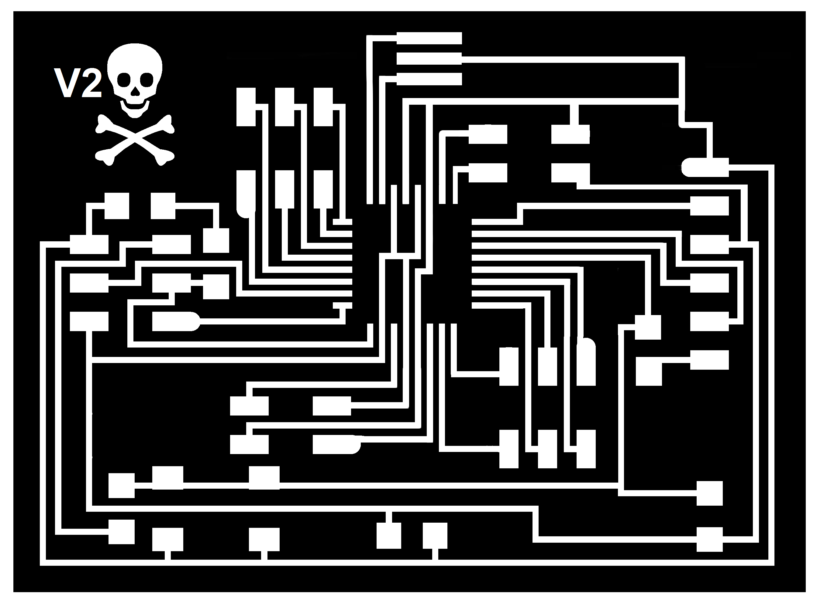
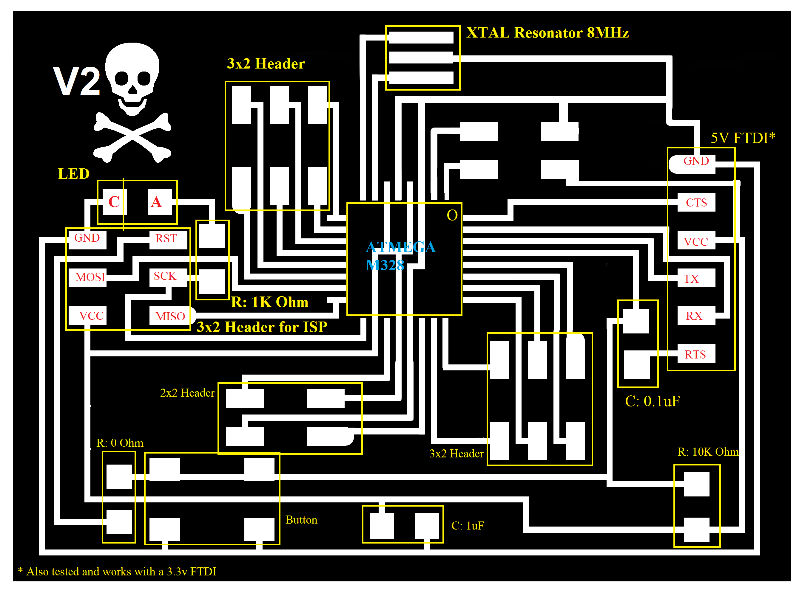
Core - Fabduino
Most instructions pass through this module (shortage in pins made me have to do some surgery, otherwise ideally this would serve has the hub in a hub-and-spoke topology).
Details on how to make the Fabduino are described in the Input Devices Week page, including specific installation instructions, a board file, pinout and other important data. Minor changes were made in the V2 version milled for this project, most importantly the removal of both temperature sensors for the sake of more pins.
The module is connected to the LCD display and is used to store data and provide instructions to the peripherals.
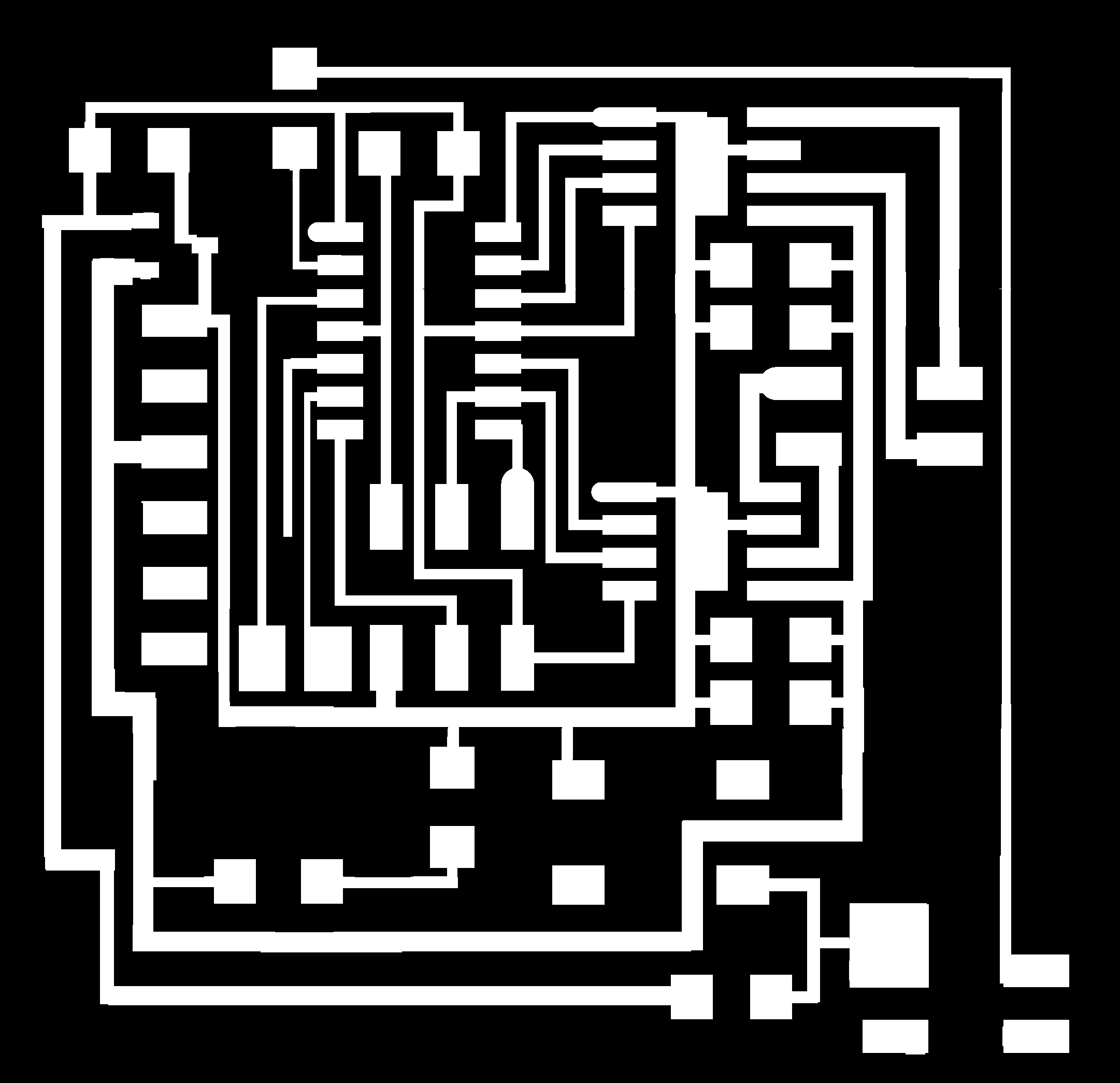
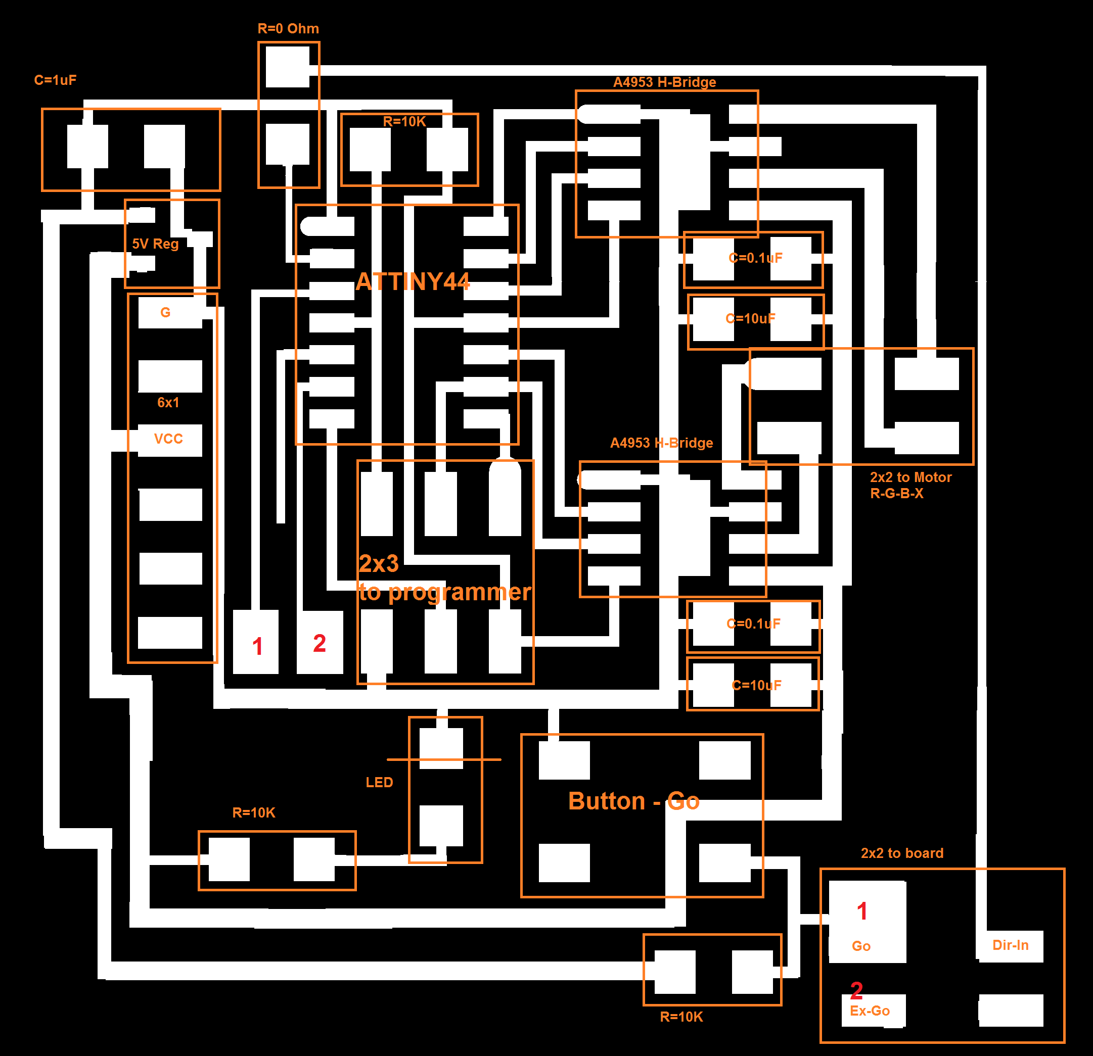
Motor Module
This module operates two H-Bridges that run the bipolar 4-wire motor. The two main parameters this module accepts as inputs are the Go instruction and the Direction instruction (rotate clockwise or counterclockwise).
Details on how to make this module are described in the Output Devices Week page, including specific installation instructions, other hackables, pinout and other important data. Very minor changes were made in the V2 version milled for this project, most importantly connecting more pins in the ATTINY-44 to the outside world to allow for more modularity.
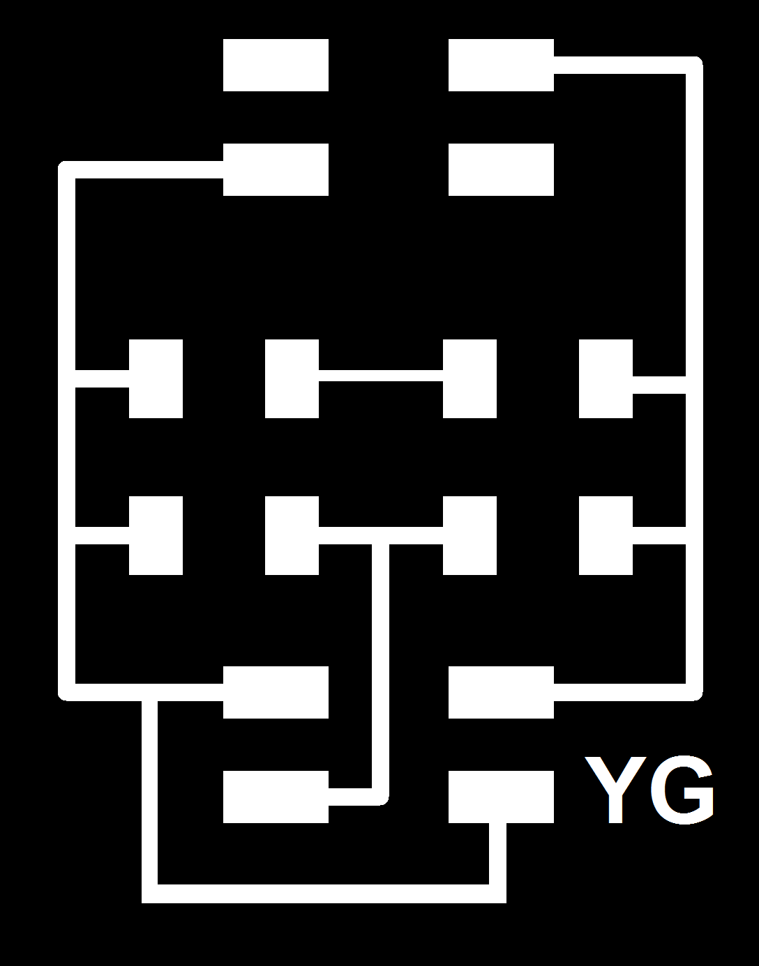
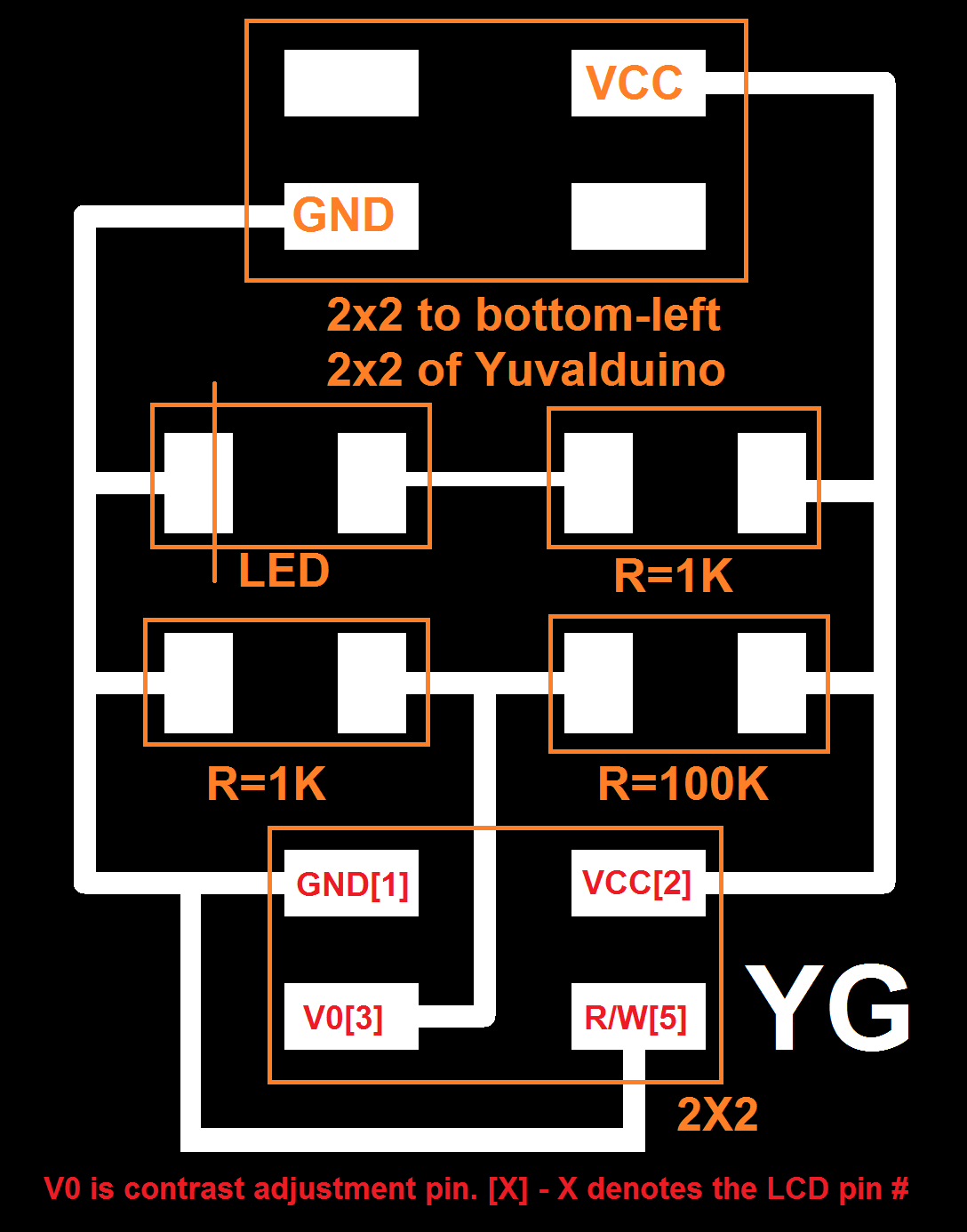
LCD with voltage converter
The LCD displays the direction control, as well as number of rotations made so far since the last replacement, and the device’s IP address.
In a basic configuration, 10 wires are enough to operate the LCD: 6 data pins, and 4 pins to control the brightness of the screen. A small breakout board does just that. Details on connectivity and this module are also described in the Output Devices Week page. This board was left unchanged for the final project:
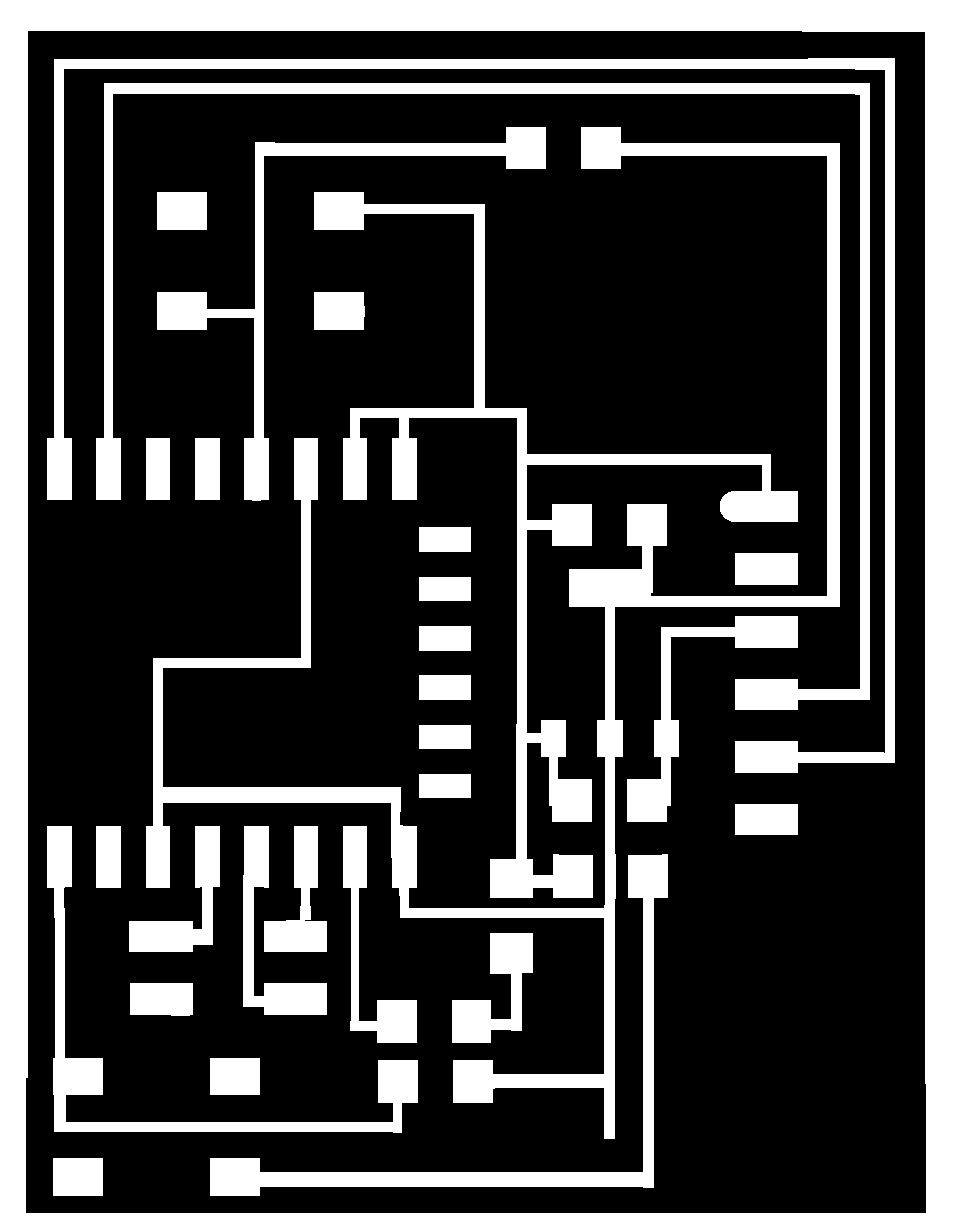
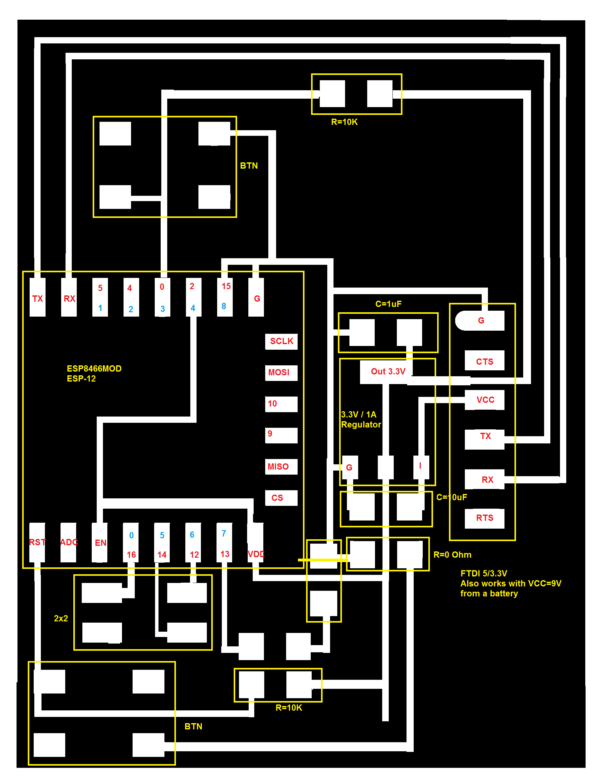
Wifi Module
The Wifi Module is a ESP-8266 board that is used as a network server. It allows control over lighting and external dispensing.
Ideally, the wifi module would have a serial connection to the main fabduino. I tried to work on this for several hours but couldn’t get the handshake right (baud rate) so for now am doing a bypass through a host computer.
Details on connectivity and this module are also described in the Networking Week page, including my endless struggle with AT vs. NodeMCU, reflashing the device and other issues. This board was left unchanged for the final project:
Other
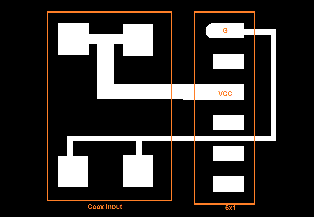
A smaller PCB (not described in above image) converts a 9V coaxial input to a 6-pin FTDI interface (just for the sake of the connector):
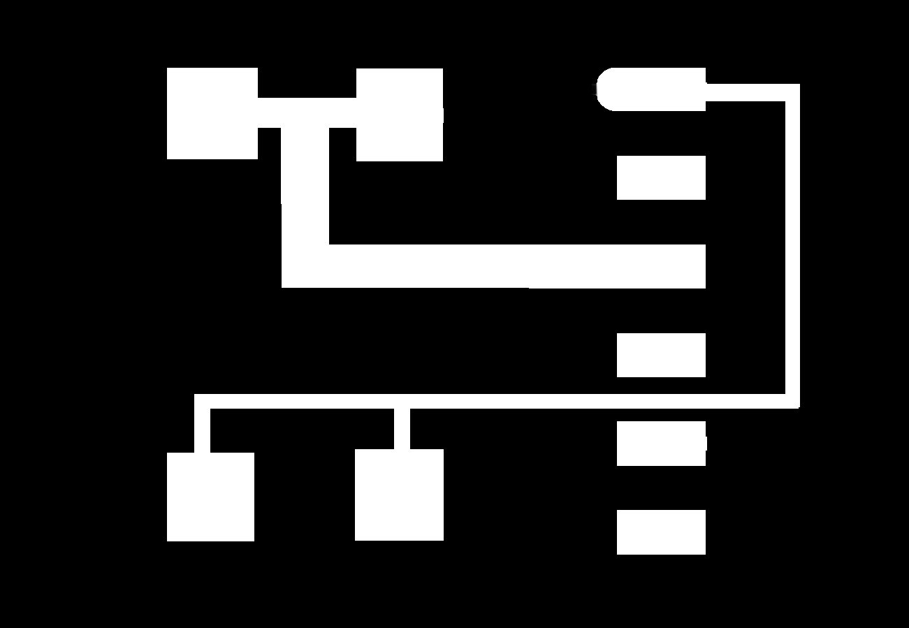
For the switch, I used a generic Radio Shack switch we had at the lab. The two buttons were purchased from Amazon.
Software
Code for Fabduino
See below for the fabduino code, which is also downloadable here. More details about LCD connectivity and button debouncer are in the Input Devices Week page. For this project, I added support for direction pin (which is then routed to the motor module and displayed via the lcd), as well as serial connection support for the host to display the IP address the Wifi module has acquired.
#include <LiquidCrystal.h>
#include <SoftwareSerial.h>
/*
LetIoT
For use with Yuvalduino
Yuval Gonczarowski
HTMAA
December 2016
RS = My 5, LCD 4
LCD E = My 7, LCD 6
D4 = My 10, LCD 11
D5 = My 9, LCD 12
D6 = My 8, LCD 13
D7 = My 6, LCD 14
R/W = GND LCD 5
VSS = GND
VCC = 5V
Wiper to LCD V0
*/
int Dir_In_Pin = 4;
int Dir_Out_Pin = 3;
//int LEDPin = 13;
int externalGoIn = 13;
int externalGoOut = 12;
int RotateButtonPin = 11;
int numRotations = 0;
int iter = 0;
int current_stateBtn;
int last_stateBtn;
int current_ex;
int last_ex;
char myip[15];
int myipindex = 0;
char incomingByte = 0; // for incoming serial data
unsigned long lastDebounceTimeBtn = 0; // the last time the output pin was toggled
unsigned long lastDebounceTimeEx = 0; // the last time the output pin was toggled
unsigned long debounceDelayBtn = 20; // the debounce time; increase if the output flickers
unsigned long debounceDelayEx = 20; // the debounce time; increase if the output flickers
LiquidCrystal lcd(5, 7, 10, 9, 8, 6);
// the setup function runs once when you press reset or power the board
void setup() {
lcd.begin(16, 2);
lcd.print("Searching IP...");
Serial.begin(9600);
Serial.write("Welcome, Debugger!");
// initialize digital pin LED_BUILTIN as an output.
// pinMode(LEDPin, OUTPUT);
pinMode(RotateButtonPin, INPUT);
pinMode(Dir_In_Pin, INPUT);
pinMode(externalGoIn, INPUT);
pinMode(externalGoOut, OUTPUT);
pinMode(Dir_Out_Pin, OUTPUT);
current_stateBtn = digitalRead(RotateButtonPin);
last_stateBtn = current_stateBtn;
current_ex = digitalRead(externalGoIn);
last_ex = current_ex;
}
int GoHandler(unsigned long* LDT, unsigned long* DD, int* current, int* last, int pin)
{
int reading = digitalRead(pin);
if (*last != reading) {
*LDT = millis();
}
if ((millis() - *LDT) > *DD) {
// whatever the reading is at, it's been there for longer
// than the debounce delay, so take it as the actual current state:
// if the button state has changed:
if (reading != *current) {
*current = reading;
// only toggle the LED if the new button state is HIGH
if (*current == LOW) {
++numRotations;
}
}
}
*last = reading;
}
// the loop function runs over and over again forever
void loop() {
digitalWrite(externalGoOut, digitalRead(externalGoIn));
// digitalWrite(LEDPin, HIGH);
delay(10);
// digitalWrite(LEDPin, LOW);
delay(10);
GoHandler(&lastDebounceTimeBtn, &debounceDelayBtn, ¤t_stateBtn, &last_stateBtn, RotateButtonPin);
GoHandler(&lastDebounceTimeEx, &debounceDelayEx, ¤t_ex, &last_ex, externalGoIn);
lcd.setCursor(0, 1);
lcd.print(numRotations);
lcd.setCursor(12,1);
if (digitalRead(Dir_In_Pin) == HIGH) {
lcd.print("CW ");
digitalWrite(Dir_Out_Pin, HIGH);
}
else {
lcd.print("CCW");
digitalWrite(Dir_Out_Pin, LOW);
}
// Loop runs every 20 ms. Every 10 seconds - refresh IP address
if (iter == 500) {
while (Serial.available() > 0) {
incomingByte = Serial.read();
if (((incomingByte >= '0') && (incomingByte <= '9')) || (incomingByte == '.')) {
myip[myipindex++] = incomingByte;
}
} // say what you got:
if (myipindex > 0) {
while (myipindex < 16){
myip[myipindex++] = ' ';
}
}
lcd.setCursor(0, 0);
Serial.println(myip);
lcd.print(myip);
myipindex = 0;
iter = 0;
}
iter++;
}
Code for Wifi Module
The Wifi module code was written in Lua (again, on my struggles with Lua, see the Networking Week page, including instructions how to install esplorer and reflash the device. The init.lua file can be downloaded here (remember to rename to init.lua for automatic load-on-reset). For the sake of final project demonstration, I purchased a $15 router and named it HTMAA_Yuval with the password described below.
wifi.setmode(wifi.STATION)
wifi.sta.config("HTMAA_Yuval","fablab123")
print(wifi.sta.getip())
NumUses=0
if srv~=nil then
srv:close()
end
led1 = 7
externalGo = 0
gnd_led = 6
vcc_led = 5
gpio.mode(led1, gpio.OUTPUT)
gpio.mode(externalGo, gpio.OUTPUT)
gpio.mode(gnd_led, gpio.OUTPUT)
gpio.mode(vcc_led, gpio.OUTPUT)
gpio.write(externalGo, gpio.LOW)
gpio.write(gnd_led, gpio.LOW)
gpio.write(vcc_led, gpio.LOW)
srv=net.createServer(net.TCP)
srv:listen(80,function(conn)
conn:on("receive", function(client,request)
local buf = "";
local _, _, method, path, vars = string.find(request, "([A-Z]+) (.+)?(.+) HTTP");
if(method == nil)then
_, _, method, path = string.find(request, "([A-Z]+) (.+) HTTP");
end
local _GET = {}
if (vars ~= nil)then
for k, v in string.gmatch(vars, "(%w+)=(%w+)&*") do
_GET[k] = v
end
end
buf = buf.."<h1> eToiler ePaper eDispenser</h1>";
buf = buf.."<p>My IP is ";
buf = buf..tostring(wifi.sta.getip());
buf = buf.."</p>";
buf = buf.."<p>Number times used since last reset: ";
buf = buf..tostring(NumUses);
buf = buf.."</p>"
buf = buf.."<p> Get more on <a href=\"https://www.amazon.com/s/ref=nb_sb_noss?url=search-alias%3Daps&field-keywords=Toilet+Paper\">Amazon</a> </p>";
buf = buf.."<p>Light: <a href=\"?pin=ON1\"><button>ON</button></a> <a href=\"?pin=OFF1\"><button>OFF</button></a></p>";
buf = buf.."<p>Dispense: <a href=\"?pin=GO1\"><button>GO</button></a> </p>";
local _on,_off = "",""
if(_GET.pin == "ON1")then
gpio.write(led1, gpio.HIGH);
gpio.write(vcc_led, gpio.HIGH);
elseif(_GET.pin == "OFF1")then
gpio.write(led1, gpio.LOW);
gpio.write(vcc_led, gpio.LOW);
elseif(_GET.pin == "GO1")then
gpio.write(led1, gpio.HIGH);
gpio.write(externalGo, gpio.HIGH);
tmr.delay(2000000);
gpio.write(led1, gpio.LOW);
gpio.write(externalGo, gpio.LOW);
end
client:send(buf);
client:close();
collectgarbage();
end)
end)
Code for Motor Module
The code for the ATTINY44 that runs the motor module is heavily based on Neil’s Hello World Bipolar example, with a few minor changes:
-
The button press command has moved to an interrupt handler
-
Support for external direction rotation was added
-
and another external go bit handler was added in the main loop.
Links to download followed by the code itself:
//
//
// hello.stepper.bipolar.44.full.c
//
// bipolar stepper mode for Yuval's TP Project
// Yuval Gonczarowski 12/15/16
//
// Based on Hello World Bipolar stepper by
// Neil Gershenfeld
// 11/21/12
//
// (c) Massachusetts Institute of Technology 2012
// This work may be reproduced, modified, distributed,
// performed, and displayed for any purpose. Copyright is
// retained and must be preserved. The work is provided
// as is; no warranty is provided, and users accept all
// liability.
//

#include <avr/io.h>
#include <util/delay.h>
#include <avr/interrupt.h>
#include <avr/pgmspace.h>

#define output(directions,pin) (directions |= pin) // set port direction for output
#define set(port,pin) (port |= pin) // set port pin
#define clear(port,pin) (port &= (~pin)) // clear port pin
#define pin_test(pins,pin) (pins & pin) // test for port pin
#define bit_test(byte,bit) (byte & (1 << bit)) // test for bit set

#define bridge_port PORTA // H-bridge port
#define bridge_direction DDRA // H-bridge direction
#define A2 (1 << PA0) // H-bridge output pins
#define A1 (1 << PA1) // "
#define B2 (1 << PA3) // "
#define B1 (1 << PA4) // "
#define button_pressed() ((!(PINA >> 7) & 1))
#define direction_ccw_set() ((PINB >> 1) & 1)
#define external_go() (PINB >> 2)
#define on_delay() _delay_us(25) // PWM on time
#define off_delay() _delay_us(5) // PWM off time
#define long_delay() _delay_ms(2000) // Long delay between external go busy-wait
#define PWM_count 100 // number of PWM cycles
#define step_count 5 // number of steps

void set_button_interrupt();
void step_cw();
void step_ccw();
void go(uint8_t dir);

static uint8_t count;
static uint8_t went_counter;
ISR(PCINT0_vect) {
   //
   // pin change interrupt handler
   //
   if (!button_pressed()) { // avoid interrupt on both push and release
       set_button_interrupt();
       return;
   }
   go(direction_ccw_set());
   set_button_interrupt();
}

void go(uint8_t dir)
{
    static uint8_t i, j;
      for (i = 0; i < step_count; ++i) {
         if (dir) {
            for (j = 0; j < i; ++j)
                step_cw();
            }
         else {
            for (j = 0; j < i; ++j)
                step_ccw();
         }
      }
}
void set_button_interrupt()
{
   //PA7 = PCINT10
   // Set GIMSK pin PCIE0 to high to enable PCINT[7:0]
   set(GIMSK, 1 << PCIE0);
   set(PCMSK0, 1 << PCINT7);
   sei();
}

//
// A+ B+ PWM pulse
//
void pulse_ApBp() {
  clear(bridge_port, A2);
  clear(bridge_port, B2);
  set(bridge_port, A1);
  set(bridge_port, B1);
   for (count = 0; count < PWM_count; ++count) {
      set(bridge_port, A1);
      set(bridge_port, B1);
      on_delay();
      clear(bridge_port, A1);
      clear(bridge_port, B1);
      off_delay();
      }
   }
//
// A+ B- PWM pulse
//
void pulse_ApBm() {
  clear(bridge_port, A2);
  clear(bridge_port, B1);
  set(bridge_port, A1);
  set(bridge_port, B2);
   for (count = 0; count < PWM_count; ++count) {
      set(bridge_port, A1);
      set(bridge_port, B2);
      on_delay();
      clear(bridge_port, A1);
      clear(bridge_port, B2);
      off_delay();
      }
   }
//
// A- B+ PWM pulse
//
void pulse_AmBp() {
  clear(bridge_port, A1);
  clear(bridge_port, B2);
  set(bridge_port, A2);
  set(bridge_port, B1);
   for (count = 0; count < PWM_count; ++count) {
      set(bridge_port, A2);
      set(bridge_port, B1);
      on_delay();
      clear(bridge_port, A2);
      clear(bridge_port, B1);
      off_delay();
      }
   }
//
// A- B- PWM pulse
//
void pulse_AmBm() {
  clear(bridge_port, A1);
  clear(bridge_port, B1);
  set(bridge_port, A2);
  set(bridge_port, B2);
   for (count = 0; count < PWM_count; ++count) {
      set(bridge_port, A2);
      set(bridge_port, B2);
      on_delay();
      clear(bridge_port, A2);
      clear(bridge_port, B2);
      off_delay();
      }
   }
//
// clockwise step
//
void step_cw() {
   pulse_ApBp();
   pulse_AmBp();
   pulse_AmBm();
   pulse_ApBm();
   }
//
// counter-clockwise step
//
void step_ccw() {
   pulse_ApBm();
   pulse_AmBm();
   pulse_AmBp();
   pulse_ApBp();
   }

int main(void) {
   //
   // main
   //
   //
   // set clock divider to /1
   //
   CLKPR = (1 << CLKPCE);
   CLKPR = (0 << CLKPS3) | (0 << CLKPS2) | (0 << CLKPS1) | (0 << CLKPS0);
   //
   // initialize bridge pins
   //
   clear(bridge_port, A1);
   output(bridge_direction, A1);
   clear(bridge_port, A2);
   output(bridge_direction, A2);
   clear(bridge_port, B1);
   output(bridge_direction, B1);
   clear(bridge_port, B2);
   output(bridge_direction, B2);
   //
   // main loop
   set_button_interrupt();
   went_counter = 0;
   //
   while (1) {
    if (external_go())
    {
        go(direction_ccw_set());
        go(direction_ccw_set());
        go(direction_ccw_set());
        long_delay();
    }
   }
}
Serial host bypass
My original intention was to connect the TX and RX of the Wifi module to two pins on the fabduino, using the SoftwareSerial library, in an effort to transfer the IP address to the LCD screen after it is acquired.
I found the Software serial package to be unreliable - it kept going out of sync despite several efforts to make the process more efficient and use a very low baud rate. Giving up, I ended up using a bypass with a host computer. This code is to be run every time reset is pushed, to enable the above feature (download):
#!/usr/bin/python
import sys
import serial
import time


portwifi = "/dev/tty.usbserial-FT9KZ5BU"
speedwifi = 115200
portfab =  "/dev/tty.usbserial-FT94TLAR"
speedfab = 9600
ser_wifi = serial.Serial(portwifi, speedwifi)
ser_wifi.setDTR()
ser_fab = serial.Serial(portfab, speedfab)
ser_fab.setDTR()
time.sleep(5)

ser_wifi.flushInput()
ser_wifi.flushOutput()

ser_wifi.write(b'=wifi.sta.getip()\r\n')
time.sleep(1) # wait a sec
myip = ""
while (ser_wifi.inWaiting()):
    byte = ser_wifi.read();
    myip += byte
    sys.stdout.write(byte);
sys.stdout.write('\n')
myip = myip.split( )[1].split(' ')[0]
print myip
ser_fab.write(myip+'\r\n')
entered = 0
while(1):
    while (ser_fab.inWaiting()):
        byte = ser_fab.read();
        sys.stdout.write(byte);
        entered = 1;
        time.sleep(0.1) # wait a bit
    if (entered):
        sys.stdout.write('\n')
        entered = 0;
Design and enclosure
Box
The box was milled on a Shopbot using vCarve. My original intention was to 3rd print the box, but this ended up being a 17-hour job which would be too long (lesson learned: don’t to it in the last week). So after I sent the print I went ahead and milled the box on the shopbot - it actually looked pretty nice so I went with that.
Here’s (3dm, stl) the 3D model of the box.
For vCarve, I used a 2D flat model of the 5 sides (useful Rhino commands: DupEdgeMesh and Explode) and milled it on a nice piece of wood we had. Download DXF
Modelo:
Box By Yuval Gonczarowski Modelo »
Roller
The Roller was 3D printed, with a precise diameter to fit the connector used on the motor, and room for two screws.
Here’s (3dm, stl) the 3D model of the roller.
The printer of choice was the 3D Wox, because it was available and because I haven’t used it thus far. Printing was literally as easy as pushing a button. Supports were fairly easy to remove.
Modelo:
Roller By Yuval Gonczarowski Modelo »
Other Side Holder
The holder on the other side is detachable, allowing the user to replace the toilet paper roll when finished. My original thought (as described in the week 1 page) was to use a spring for this, but I ended up using press-fit with a simple puzzle piece design, copied from my efforts during 3D Printing week.
Here’s the 2D flattened DXF Model: Download DXF

I used a nice piece of wood found at the lab. Lessons from here include paying special attention to milling from outside/inside (made that mistake once) and profile/pocket toolpaths. Also, never trust others! The 0.125” endmill was defined in vCarve to have a 0.25” diameter. Argh!
Velcro
Lastly, order inside the box is extremely important, especially given the large amount of wires (as a result of the modular build). I used small pieces of velcro to make sure nothing remains “floating” inside the box.
Photos
Connecting things:

Push the button:

About to wrap it all up::

Yuval and a friend:
