Week Nine: Input Devices
Built a fully functional Arduino from scratch, and measured the temperature. It’s getting hot in here!
Background
Our assignment this week was to measure something: add a sensor to a microcontroller board that we have designed, and read it.
Fabduino
Up until now I was working directly with embedded C, and never with the Arduino software. This week I wanted to create a fully functional Arduino with an ATMEGA chip.
There are many “fabduino” tutorials in the lab, and most of them refer to a broken-link to Anna(?)’s stuff. Gathering information from here and there, I’ve decided to follow here with a guide the summarizes my main takeaways, problems, and solutions - in creating a working Arduino that can be programmed and then be used standalone:
Milling
I took a common Fabduino layout and removed one of the 2x2 headers, who were replaced with the two temperature sensors.
Special note: I admit I did some last-minute adjustment with MSpaint. We should be very careful when using mspaint, as it overwrites a lot of metadata on files! One important piece that is overwritten is the canvas size, or ratio in actual inches (dpi). So, if you use the file below, please note the below details (useful for fabmodules):
DPI: 1265.9
2688 x 1990 px
53.930 x 39.926 mm
2.123 x 1.572 in
Soldering
Wasn’t fun. I had to re-mill because I accidentally yanked out one of the traces. After a lot of trial and error, the only tip I can provide here is to be patient with the soldering iron and wait until everything is hot, not only the pen.
Programming
There was a LOT of trial and error here, so I’ll detail step-by-step:
- Connect FTDI cable from Fabduino to computer.
- Connect AVR programmer (Programming failed with my fabISP, and others’ fabISPs) to your computer, and connect via ribbon to the 3x2 header. Make sure the red wire is connected to MISO.
- Download the Arduino IDE. Install.
- If everything is connected properly, the AVR programmer light should turn green.
This next step is tricky: Our board is a custom board and as such we need to define it in the Arduino software database. We need to locate boards.txt. In Windows, this would be in our install directory; under mac we need to find the dmg file -> right click -> show package contents -> Contents -> Java -> hardware -> arduino -> avr -> boards.txt
Open this file with your favorite txt editor and add the below code between any two boards:
##############################################################

yuval.name= Yuval's Fabduino
yuval.upload.tool=avrdude
yuval.upload.protocol=arduino

yuval.bootloader.tool=avrdude
yuval.bootloader.unlock_bits=0xFF
yuval.bootloader.lock_bits=0xCF

yuval.build.board=AVR_PRO
yuval.build.core=arduino
yuval.build.variant=eightanaloginputs
## Yuval's Fabduino (3.3V, 8 MHz) w/ ATmega328
## --------------------------------------------------
yuval.menu.cpu.8MHzatmega328=ATmega328 (3.3V, 8 MHz)

yuval.menu.cpu.8MHzatmega328.upload.maximum_size=30720
yuval.menu.cpu.8MHzatmega328.upload.maximum_data_size=2048
yuval.menu.cpu.8MHzatmega328.upload.speed=57600

yuval.menu.cpu.8MHzatmega328.bootloader.low_fuses=0xFF
yuval.menu.cpu.8MHzatmega328.bootloader.high_fuses=0xDA
yuval.menu.cpu.8MHzatmega328.bootloader.extended_fuses=0xFD
yuval.menu.cpu.8MHzatmega328.bootloader.file=atmega/ATmegaBOOT_168_atmega328_pro_8MHz.hex

yuval.menu.cpu.8MHzatmega328.build.mcu=atmega328p
yuval.menu.cpu.8MHzatmega328.build.f_cpu=8000000L
I had to create this from scratch, since all I could find are Fabduinos that use the 168 ATmega or a 20Mhz resonator (we’re out of stock in the lab). I also had to change the fuse configuration which required a lot of digging into the datasheet to avoid errors/warnings.
Anyhow, save boards.txt and start the Arduino program.
The only thing we need to do with the AVR programmer is to burn the bootloader. So let’s do that:
- Tools->Board->”Yuval’s Fabduino” (that’s what we did with boards.txt!)
- Processor: ATmega328, 3.3V, 8MHz (should be the only option)
- Port: Select the FTDI port (this is determined by which cable you use)
- Programmer: AVRISP mkII (the fabISP should work if you choose USBtinyISP here; none of the fabISPs that I tried worked with this)
- Burn bootloader.
You should get 0 errors, 0 warnings, and a message that the bootloader burned successfully. Congrats! Now we no longer need the AVR programmer or the 3x2 header.
Pinout
The next question is: How do we handle pins from the Arduino IDK?
This is the datasheet for the ATMEGA. On page 3, in the bottom right, I found the pinout for the package that I used.
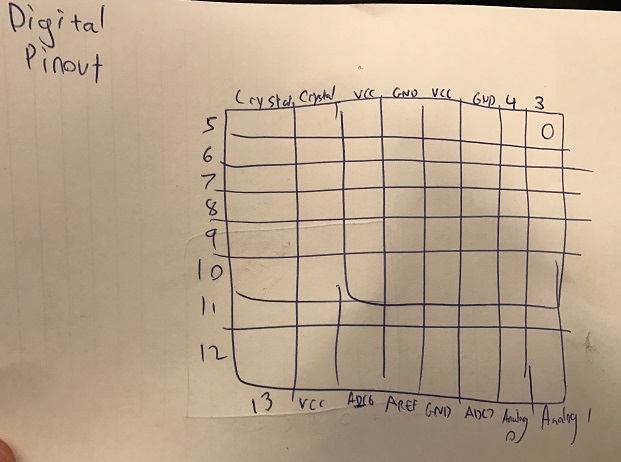
This is the Arduino pin mapping for the ATMEGA328. Note that “Digital pin 4”, for example (what we would use as pin 4 in the Arduino tools) is not the same as Schematics Pin 4., which is actually “Digital pin 2”. Confusing? Yes.
Too confusing, that I drew a little cheat sheet for myself:
Code
/*
  Temperature Sensor
  For use with Yuvalduino
  Yuval Gonczarowski
  HTMAA
  November 2016
*/

int NTCPin = 4;
int NTCValue = 0;
int RTDPin = 3;
int RTDValue = 0;
int LEDPin = 13;

// the setup function runs once when you press reset or power the board
void setup() {
  Serial.begin(9600);
  // initialize digital pin LED_BUILTIN as an output.
  pinMode(LEDPin, OUTPUT);
}

// the loop function runs over and over again forever
void loop() {
  digitalWrite(LEDPin, HIGH);
  delay(1000);
  digitalWrite(LEDPin, LOW);
  delay(1000);
  NTCValue = analogRead(NTCPin);
  RTDValue = analogRead(RTDPin);
  Serial.print("The NTC / RTD Temperature is: ");
  Serial.print(NTCValue,DEC);
  Serial.print ('/');
  Serial.print(RTDValue,DEC);
  Serial.print('\n');
}
The LED blinks to make sure we’re alive, and we are reading the analog value of the NTC and RTD pins and printing them to screen.
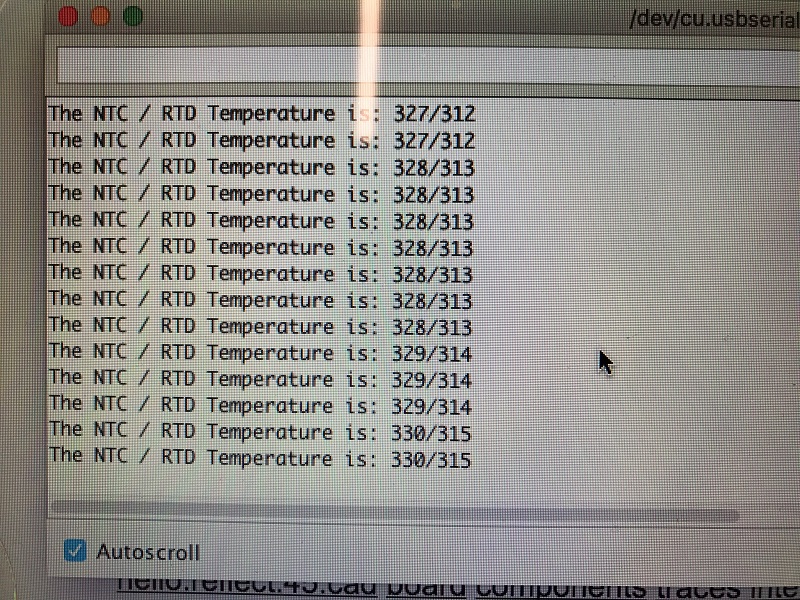
When opening the comm port in room temperature settings, we see a fairly stable read:
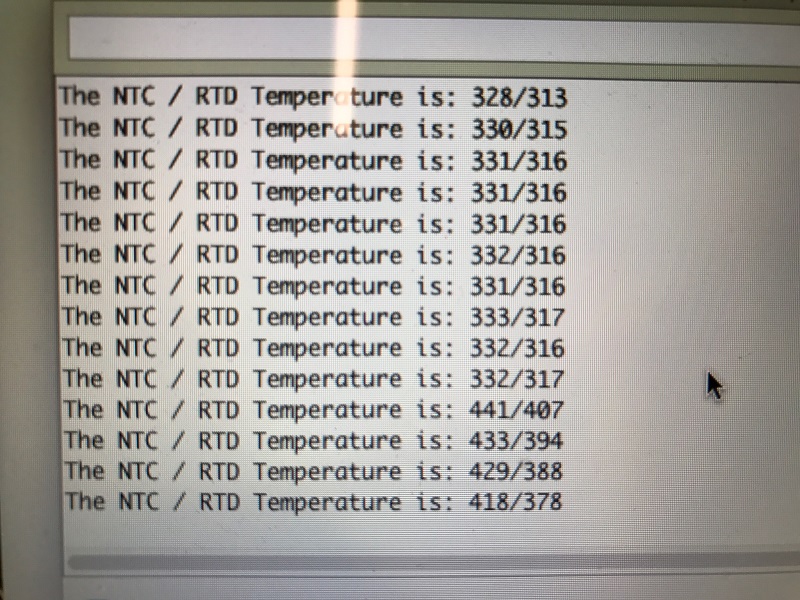
After I place my thumb on the sensors to heat them a little bit, we see the numbers going up:
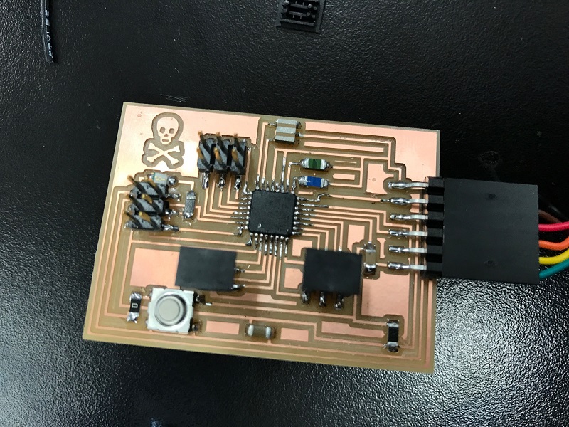
Here’s the device:


