Week Fifteen: Final Project Submission
Meet TelIoT: The Toilet Paper Revolution

Dabbling with Hardware
Meet TelIoT: The Toilet Paper Revolution
Modular machine machining. Deus Ex Machina?
WiFi Web Server at your service.
Wrote a small program to interface with input- and output-devices
Operating a motor and an LCD together with daughterboards
This week our assignment was to work with output devices: Motors, LCDs, etc.
My final project is going to be a “next gen” toilet paper dispenser, so this was a great week to make progress on this front.
I focused my efforts on
My first task was to make the LCD work. This took over a day! Originally I looked at this design from the Arduino tutorial and aimed to replicate it. I made a daughterboard with two 2x5 connectors. Using the potentiometers that we have at the lab proved to be a bad idea; they are easily breakable and seemed like I could not get anything right. I struggled with this for several hours, and here is what I did wrong:
Also, here’s a tip. No, not a tip. A command. An order: Put an LED on any board you make!
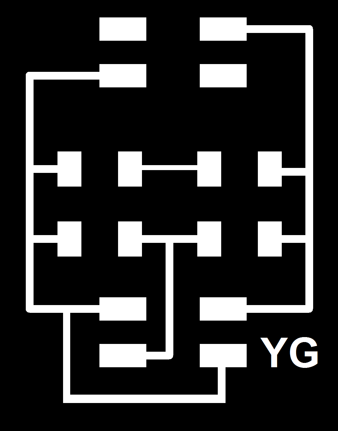
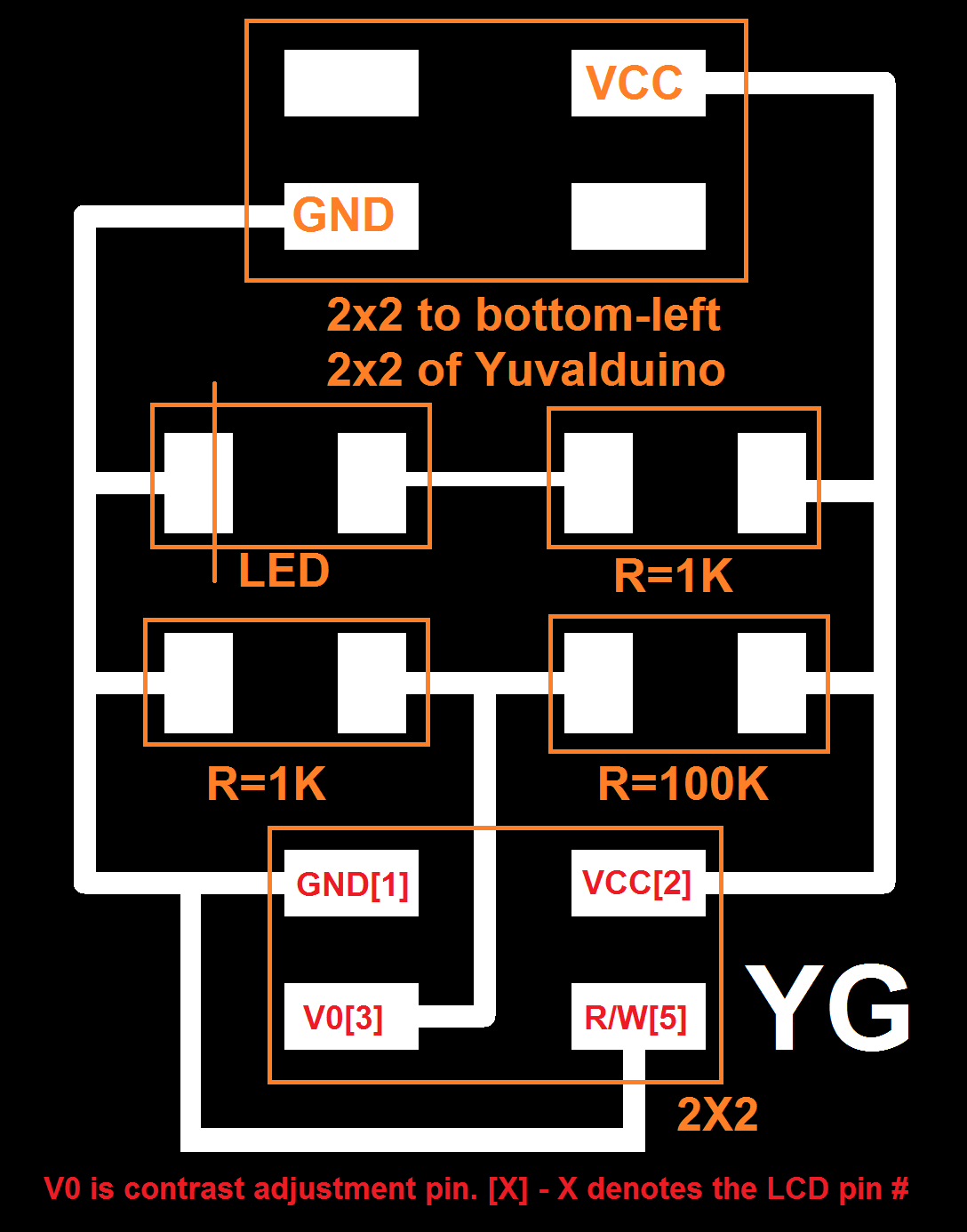
I ended up making a miniature daughterboard, that is pretty much only used to set the right contrast voltage. I shamelessly copied the value of the resistors and the connectivity from Neil’s Hello World LCD example. The Fabduino code was later taken from the above example and adapted to my needs. Here are some links (dpi 1500 - careful):
4 wires connect from the daughter-board to the LCD: VCC, V0 (Contrast) and 2xGND (actual ground and setting R/W to 0).
The other 6 wires are data pins and they are connected directly to the Yuvalduino. If you are using my code, here’s how the wire should look:

Here’s a photo of how it all looks (code to follow in a sec after I explain what I did with the motor):

Here too, a lot of failures to learn from and about 5 failed milled boards. I decided to use the step motor because the final project will require me to determine precisely the speed and length of the turn. I used as a basis Neil’s bipolar motor and board, but had to make some adjustments. There is a lot of data around the fab sites on the step motor, but here are some important things I had to spend a lot of time looking for.
colors (some keywords if you search for this later on - hello from 2016!: colors, step motor colors, step motor wires, step motor coloring, step motor pinout):

The step motor requires a 9V power (I used a 9v battery, or as I call it, a ‘we all put our tongue there at least once’ battery). Use thicker traces because they will draw A LOT of current.
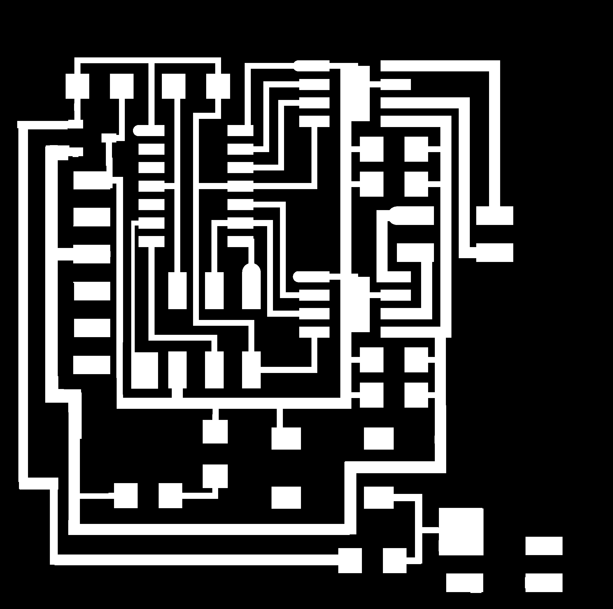
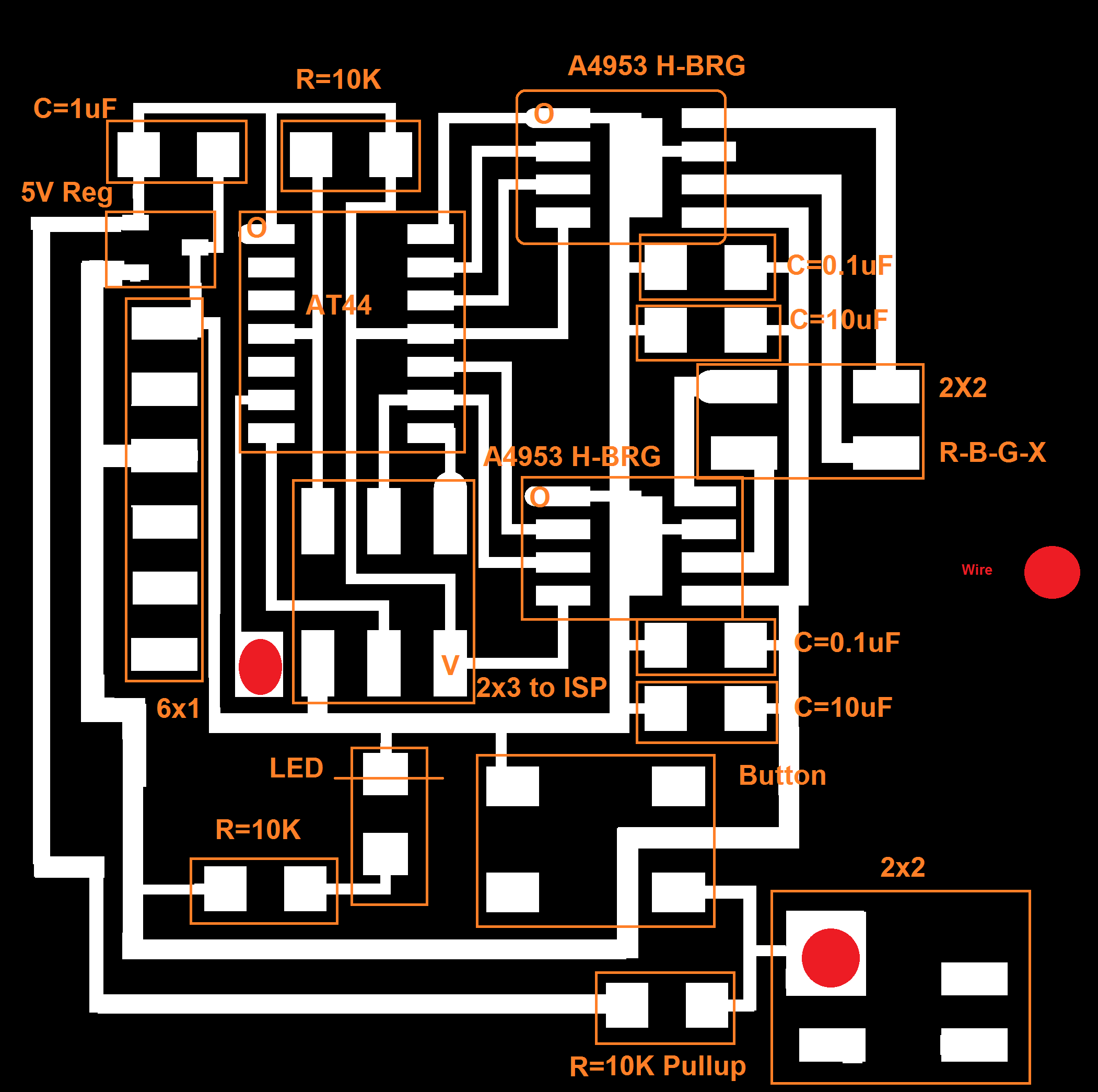
Here are the files for this daughter board (dpi should be 1269.289 - careful):
Some cheats regarding these files:
See the red dot? Solder some insulated wire (tips exposed) between the spots. I originally couldn’t find any easy way to transfer data from the new button to the old YuvalDuino so made this bypass. It works.
I changed the 9v/gnd input to look like an FTDI input, and then used crimps for the battery to fit.
Here’s how you should connect the motor (use this for Neil’s board too):

Another key thing on the Hardware side: We have two voltage sources: The Yuvalduino takes 5v from the computer and the motor daughter board takes 9v from the battery. The information regarding the push button is transferred from one board to another. To do this YOU NEED COMMON GROUND. Find a GND pin on both boards and connect it via wire. Otherwise weird stuff happens. Trust me on this.
After several failed attempts to work only with my fabduino devices I decided to use an attiny 44 to control the step motor, but to transfer data between it and the YuvalDuino. Given that Neil’s code is in C, I used C.
I added button support and added an interrupt mechanism for the button: the motor doesn’t run on an infinite loop anymore, but only when the button is pushed.
And here’s a video that shows the motor working as a standalone device:
Finally, for the YuvalDuino code. On the push of the button (push data is transferred via the bottom-right connector on the daughterboard), in addition to the motor rotating a tad, we also update the number of rotations on the LED. This is great because eventually this will tell us when we need to replace the TP in the house. The reset button resets the count.
For this, in addition to creating common ground, I also needed to write a short debouncer for the button to stay stable and not increment the count when I’m not pushing.
Here’s the Arduino Code with debouncer, button, and LCD support
Here’s a photo of everything together:

And here’s a video of everything together!
Yay.
Burlap + Epoxy + Vacuum + Patience = Rough and strong!
Built a fully functional Arduino from scratch, and measured the temperature. It’s getting hot in here!
Make your own Machu Picchu!
An electronic lock, password protected.
Or, if the big ShopBot is always used by others - Make Something Medium!
There’s making Hardware, and there’s making it interact with you!
I have a new nephew, and the family tradition is to do something with it.
See my face in 3D.
Wow, what a weekend - I made a fully working USB device, literally from scratch.
We were asked to design, make, and document a parametric press-fit construction kit, accounting for the lasercutter kerf, which can be assembled in multiple ways.
Our assignment this week was to cut anything on the vinyl cutter; this is a shameless ad for YG Acoustics.
Our assignment for the first week was to model (raster, vector, 2D, 3D, render, animate, simulate, …) a possible final project, and post it on our class page.
Added networking capabilities, as detailed in Networking Section. Main protocol determined, still need to rewrite code on the ATTINY44 on the step motor to allow clockwise and counterclockwise selection from the web interface.
Good progress this week - as detailed in the Output Devices Section. A bit more fine tuning required on electronics, but it’s time to start thinking about the casing.
After receiving feedback from Neil during the last class, I’ve decided to focus on two main features:
Rotation: At the push of a button, the cylinder will be able to rotate to a pre-determined extent
USB charging
My wife is always the one with the ideas. She suggested anything from minor trampolines to funky office supplies, but I am more practical: our toilet paper dispenser broke the other day; I felt it should be a good device to start learning with (some cylinders, a spring, and to-scale modeling)
As a potential final project, if this ends up to be it, I could add cool features to it like USB charging, speakers and BlueTooth support, FM radio and even a servo that will dispense the paper at the push of a button.
Electronics will come later - today we’re all about modeling.
Here are some photos of the holder of what was once the dispenser. My aim, as a first step, is to fill in the missing piece.


I started by just drawing for myself the basic dimensions:

The base product will have an inner cylinder which will be able to fit the two metal pieces already mounted to my wall. It will actually be made of two smaller ones with a spring between them, to allow for easy insertion into the slot. An outer tube will wrap the smaller cylinder to hide the spring and to provide a better grip to the toilet paper roll, to avoid jitter as it turns.
Rastered images have finite resolution and are not as good for modeling. So for my first 2D modeling exercise I decided to go with a vector-based model. The undisputed king here is Adobe Illustrator; it costs money but like any good drug, there’s an evaluation period.
It took me about 2 hours, but here are a few images of the final result (wireframe and full):


(the actual .AI file is vectorized, of course)
Here are some lessons I learned:
Having the 2d model in my hand, I decided to proceed to 3d modeling. Weapon of choice for today: Rhino 3D. After skimming several on-line tutorials this seemed rather intuitive so I decided to give it a shot.
3D modeling is more complex and takes some time getting used to. The following tutorials are recommended:
Below are some snapshots of the process and final product (which is again, exactly to scale with how I drew it in the first place). My favorite feature here is the different Display Modes (e.g. wireframe, shaded, and ghosted). The final 3DM file is available here


At this point I decided to remodel the holders for the dispenser rather than use the two that I already have at home, hopefully with the intent of making this THE ULTIMATE DISPENSER later, and adding electronics, etc.
The key feature here is the Boolean Difference tool that Rhino offers, as is explained in this simple and effective tutorial.
Here’s a list of additional things I did:
Added a USB socket. The actual socket itself was downloaded from grabCAD, an open source CAD library. I wrapped a box around it using the BoundingBox command and then extracted the box from the holder.
Added support for hanging: Again, I found a model of a classic hinge in grabCAD. This was a bit more tricky because I had to create parallel holes in the holder itself for the nails. what I did was build three small cylinders around the hinge, move them to the big holder and then run a boolean difference tool.
Voila - the final product, TUTPD (The Ultimate Toilet Paper Dispenser) is now taking shape!
Modelo is a super cool free service that allows one to upload 3dm files and embed into websites. Here’s the final product, for your pleasure:
The purpose of this post is mostly to get to know some Markdown features and play around with text and images.
What’s this site about, and what I’ll be posting.